
An electrical drawing checklist is a quality-control tool that verifies all required engineering documents are complete before submitting plans for municipal building permits and utility connection approvals. In Alberta, a complete drawing package must include a site plan, single-line diagrams, panel schedules, fault current calculations, and an electrical load analysis signed and sealed by a registered Professional Engineer when required by local safety codes.
Essential Components of an Alberta Electrical Drawing Package
Municipalities across Alberta, including Edmonton and Calgary, enforce the Safety Codes Act alongside the Canadian Electrical Code (CEC) 2024. Plan examiners review electrical submittals to confirm public safety, system protection, and energy efficiency compliance. Omitting key drawings halts permit issuance and leads to project delays.
To pass plan review on the first submission, your engineering package must account for five distinct categories of drawings:
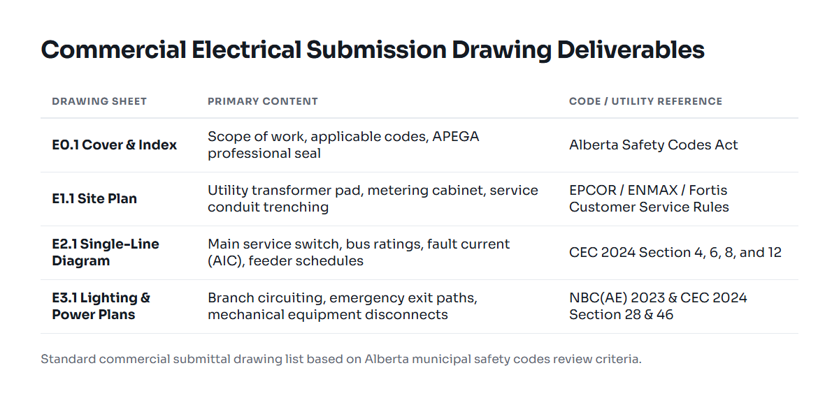
- Cover Sheet and Drawing Index: Lists project location, legal land description, scope of work, code editions applied (such as CEC 2024 and National Building Code 2023 Alberta Edition), professional seal, and permit application number.
- Electrical Site Plan: Displays property boundaries, utility points of connection (EPCOR, ENMAX, or FortisAlberta), primary and secondary trench routes, transformer pad location, clearance distances, and exterior lighting layouts.
- Single-Line Diagram (SLD): Illustrates the entire power distribution path from the utility service entrance to distribution sub-panels. It identifies main disconnect sizes, transformer ratings, bus ratings, feeder sizes, grounding conductor details, and overcurrent protective device ratings.
- Floor Plans (Power, Lighting, and Systems): Physical layouts showing receptacle placements, mechanical equipment connections, lighting fixtures, emergency exit signs, and fire alarm devices compliant with CAN/ULC-S524.
- Schedules and Calculations: Panel schedules, luminaire schedules, voltage drop tables, available short-circuit current ratings (SCCR), and a formal electrical load analysis.
Detailed Review: What the Checklist Covers
Before any drawing set leaves the office, our engineers review every sheet against strict technical criteria. To help project managers and electrical contractors review their own plans, here is how each major engineering item breaks down.
1. Define Electrical Load and Service Sizing
An electrical load is the total amount of electrical power consumed by connected equipment, lights, motors, and appliances across a facility, measured in volt-amperes (VA), kilovolt-amperes (kVA), or kilowatts (kW). In an engineering submittal, the load calculation establishes the minimum rating for service conductors, main distribution panels, and transformers.
CEC 2024 Section 8 dictates how commercial loads are calculated. Designers must apply specific demand factors rather than simply adding nameplate values together. For example, continuous commercial loads require dedicated branch sizing, while general receptacle loads use standard demand reductions.
2. Load Calculation Worked Example
Consider a typical 4,500-square-foot commercial retail unit in an Edmonton strip mall with a 120/208V, 3-phase, 4-wire electrical service. The electrical load analysis calculates connected load and applies code demand factors to determine the required main switch size:
- General Lighting Load: 4,500 sq ft at 20 VA/sq ft = 90,000 VA. Continuous commercial lighting demands 100% sizing.
- Receptacle Load: 40 duplex receptacles at standard allowance = 15,000 VA. First 10 kVA evaluated at 100%, remaining 5 kVA evaluated at 50% = 12,500 VA.
- HVAC Rooftop Unit: Total running load = 18,000 VA (non-continuous component + motor load).
- Water Heating: Electric hot water tank = 3,000 VA.
- Total Calculated Demand: 90,000 VA + 12,500 VA + 18,000 VA + 3,000 VA = 123,500 VA (123.5 kVA).
- Service Amperage Calculation: Amperes = 123,500 VA / (208 V × 1.732) = 342.8 A.
Because standard commercial switch sizes jump from 200 A to 400 A, this commercial space requires a 400 A, 120/208V, 3-phase, 4-wire main electrical service. The drawing checklist verifies that feeder cables, raceway sizing, and main breaker trip ratings are specified for 400 A capacity according to CEC Section 4 and Section 12.
3. Commercial Drawing Review Matrix
This table summarizes the core components required on each sheet, who reviews them, and the specific failure points caught during pre-submittal checks:
| Drawing Type | Key Required Items | Safety Objective | Frequent Error Identified |
|---|---|---|---|
| Site Plan | Utility transformer pad, metering location, trench routing, property lines | Ensures utility clearance and correct easement positioning | Missing FortisAlberta or EPCOR clearance envelope around pad-mount transformers |
| Single-Line Diagram | Fault current rating (AIC), bus ampacity, feeder gauges, ground electrode details | Prevents equipment damage and structural fires under short-circuit conditions | Inadequate short-circuit withstand rating on secondary distribution panels |
| Power Plans | Mechanical equipment disconnects, dedicated circuits, receptacle types | Guarantees equipment receives adequate branch protection | Omission of dedicated circuits for server equipment or RTU convenience outlets |
| Lighting Plans | Exit sign locations, emergency battery units, switching controls | Provides safe egress illumination during power loss | Photometrics omit required emergency foot-candle levels along the exit path |
| Panel Schedules | Phase load balancing, circuit breaker sizes, connected kVA, spare capacity | Avoids neutral conductor overheating and nuisance tripping | Unbalanced phase loading exceeding 10% variation across phases |
How to Use the Drawing Checklist on Your Project
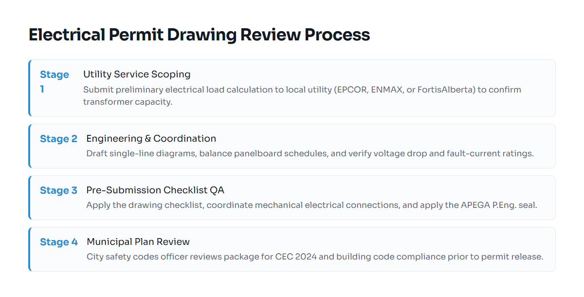
Using the drawing checklist is straightforward when integrated into the design workflow. Rather than treating it as a final hurdle on the morning of submission, apply it in three sequential stages:
- Schematic Design Stage (30% Review): Confirm the utility point of delivery and overall electrical load estimate. Review the utility fee structure and capacity requirements early with EPCOR or ENMAX to prevent expensive redesigns after equipment procurement has begun.
- Detailed Engineering Stage (60% to 90% Review): Verify conduit paths, panel schedules, fault-current values, and voltage drop across lengthy branch feeders. Designers can check branch voltage drops using an online voltage drop and SCCR calculator to verify compliance with CEC 2024 limits of 3% for branch circuits and 5% overall.
- Permit Submittal Stage (100% Quality Review): Ensure all drawings carry matching project numbers, sheet titles, dates, revisions, and professional engineering stamps from an engineer licensed with APEGA.
Reviewing drawings systematically prevents costly safety codes plan review revisions. Learn more about regional fees and permit timelines in our guide to Electrical Permit Cost in Alberta: Commercial Pricing Guide.
Field Notes and Common Permitting Traps in Alberta
Our engineering practice regularly assists contractors and architects across Alberta in addressing permit refusal notices. The majority of these rejections stem from drawing omissions rather than complex engineering failures. Here are the most frequent issues encountered:
Missing Fault-Current Calculations
Plan examiners require the available short-circuit current from the utility transformer to be stated at the main service switch and carried through downstream panels. If a utility source provides 42,000 A symmetrical fault current at the transformer secondary, downstream panels must feature an adequate Ampere Interrupting Capacity (AIC) rating or provide a tested series-rated combination. Leaving panel AIC ratings blank results in automatic plan rejection.
Disconnect Requirements for Mechanical Rooftop Units
Rooftop HVAC units require a local lockable disconnect switch within sight of the unit, alongside an external 120V maintenance receptacle fed from an independent circuit. Electrical drawings that show the power feeder terminating straight into the unit control panel without an exterior safety switch will fail safety code inspections under CEC Section 28.
Incomplete Emergency Egress Lighting Calculations
Under the National Building Code 2023 Alberta Edition, emergency lighting along paths of egress must deliver reliable illumination for a minimum duration (typically 30 minutes to two hours depending on building occupancy classification). Reviewers frequently reject drawings when battery units are detailed without calculating the connected remote head wattage, causing the emergency battery units to deplete prematurely.
Download Checklist and Next Steps
Completing a comprehensive drawing check protects your construction timeline, prevents change orders on site, and ensures your building meets safety standards before trade contractors mobilize. If you are preparing commercial permit packages in Edmonton, Calgary, or surrounding municipalities, work through our verified checklist to catch errors in the office rather than in the field.
For complex commercial, light industrial, or institutional renovations, consult with our licensed team. Explore our electrical engineering services in Alberta for single-line diagram generation, service upgrade evaluations, and sealed permit packages compliant with local utility rules. Check our engineering notes and insights for more practical technical guides covering safety codes and load calculations.
Free tools: kVA to amps calculator